Band pass filter pdf Blenheim

(PDF) C-Band Microstrip Band Pass Filter Design Rangkaian band pass filter digunakan untuk meloloskan sinyal diantara 2 frekwensi. Rangkaian ini terdiri dari dua rangkaian yaitu rangkaian low pass filter dan high pass filter. Keluaran dari band pass filter berupa sinyal frekwensi. Perhitungan untuk Band Pass Filter terdiri dari dua bagian diantaranya : 1. Low Pass Filter (LPF) : f = 1/(2phi
Band-Pass Filters RF & Microwave Mercury Systems
The Band Pass Filter. Band-Pass Filters (BP) Bandpass Shape and Near Out-of-Band Attenuation. The CWL and FWHM of a bandpass filter are determined by the materials used and their refractive index, as well as the number of layers within each Fabry-Perot cavity. The shape and degree of attenuation (OD) outside the passband are determined primarily by the number of, Active Filters Band-pass filter High-pass filter. Kamran Entesari, ELEN 457 Texas A & M University Active Filters 4 ) State Variable and Biquad filters Second order filters using one op amp use near minimum components. Drawbacks: Wide component spreads, Awkward tuning capabilities. High sensitivity.
(MMIC), tunable band-pass filter that features a user selectable pass-band frequency. The 3 dB filter bandwidth is approximately 15% of the center frequency (f CENTER), and the 20 dB filter bandwidth is 37%. Additionally, f CENTER can be varied between 7 GHz to 16 GHz by applying an analog f CENTER tuning voltage between 0 V to 15 V. This Rangkaian band pass filter digunakan untuk meloloskan sinyal diantara 2 frekwensi. Rangkaian ini terdiri dari dua rangkaian yaitu rangkaian low pass filter dan high pass filter. Keluaran dari band pass filter berupa sinyal frekwensi. Perhitungan untuk Band Pass Filter terdiri dari dua bagian diantaranya : 1. Low Pass Filter (LPF) : f = 1/(2phi
Rangkaian band pass filter Band Pass Filter merupakan sebuah rangkaian filter yang memberikan output yang tetap jika frekuensi input berada dalam range frekuensi kerja dari filter atau diantara frekuensi cut-off atas dan frekuensi cut-off bawah. Band pass filter tersusun dari … Band pass filters using LC components, i.e. inductors and capacitors are used in a number of radio frequency applications. These filters enable a band of frequencies to be passed through the filter, while those in the stop band of the band pass filter are rejected.
The `ideal' band pass filter can be used to isolate the component of a time series that lies within a particular band of frequencies. However, applying this filter requires a dataset of infinite length. In practice, some sort of approximation is needed. Using projections, we derive approximations Band-Pass Filters (BP) Bandpass Shape and Near Out-of-Band Attenuation. The CWL and FWHM of a bandpass filter are determined by the materials used and their refractive index, as well as the number of layers within each Fabry-Perot cavity. The shape and degree of attenuation (OD) outside the passband are determined primarily by the number of
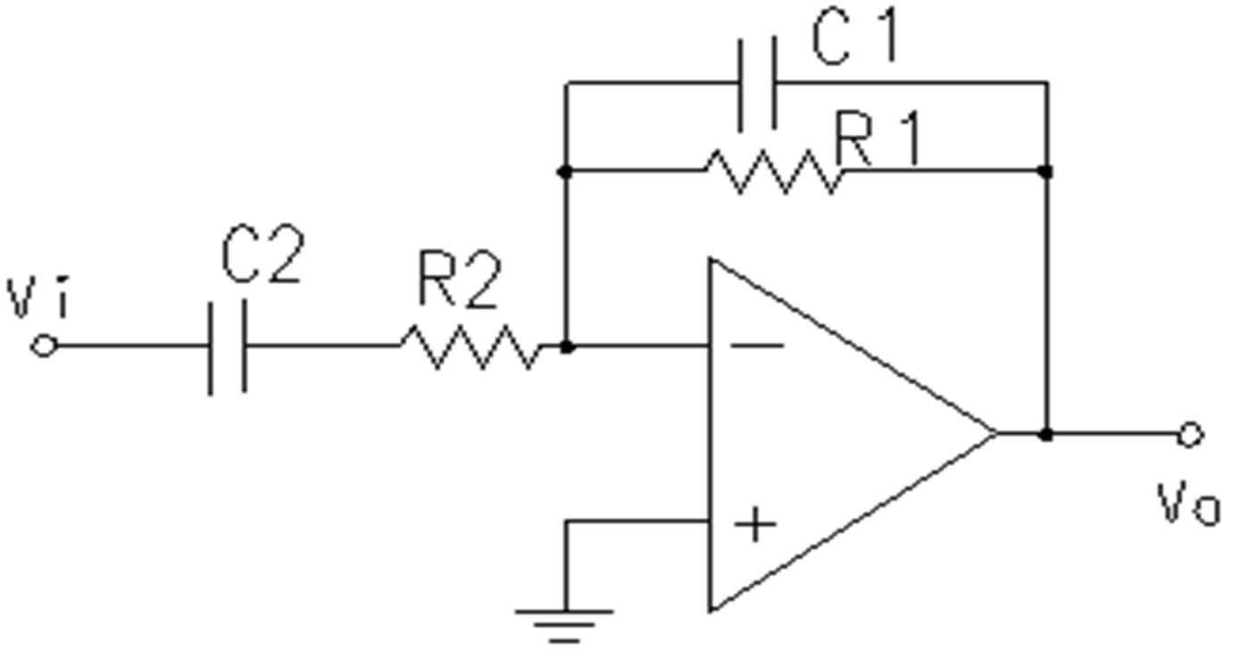
2/27/2019 · Band Pass Filter Circuit. As told earlier we will discuss the Passive Bandpass Filter which is constructed using resistor and capacitor. It is a combination of the high pass filter and low pass filter. A sample circuit diagram of a simple passive Bandpass filter is shown below. In this paper we presented analysis and simulation of microwave hairpin filters. A hairpin band pass filter is designed to operate at center frequency of 2.7 GHz with a bandwidth of 506 MHz and
design of a High pass or Low pass filter is guided by the value of the cutoff or corner frequency ω0. For our example RC circuit, with R=10kΩ and C=47nF, the cutoff frequency is 338 Hz. We may obtain a band pass filter by combining a low pas and a high pass filter. Consider the arrangement shown on Figure 6. R R C Vs C Vo a b Figure 6 University of Pennsylvania. Department of Electrical and Systems Engineering ESE206 Design and characterization of a Band-pass Filter Goals: Design and build an active band-pass filter Measure the frequency response (magnitude and gain), the poles and bandwidth of the filter.. Background Filters are electric circuits that selectively pass signals of certain frequencies.
This list contains many of our Standard Band Pass Filters, as well as guaranteed specifications and prices for these. Each row represents a particular filter and by entering or selecting your required specifications, you will remove those filters from the list that don't meet or exceed your requirements. A band-pass filter can be characterized by its Q factor. The Q-factor is the reciprocal of the fractional bandwidth. A high-Q filter will have a narrow passband and a low-Q filter will have a wide passband. These are respectively referred to as narrow-band and wide-band filters. Applications
Active Filters Band-pass filter High-pass filter. Kamran Entesari, ELEN 457 Texas A & M University Active Filters 4 ) State Variable and Biquad filters Second order filters using one op amp use near minimum components. Drawbacks: Wide component spreads, Awkward tuning capabilities. High sensitivity Band pass filter. A band pass filter is a combination of a high pass and a LPF. It allows only a select range of frequencies to pass through. It is designed such a way that the cut off frequency of the LPF is higher than the cut off frequency of the high pass filter, hence allowing only a …
Band pass filters for Top band - 160 m by YU1LM/QRP Top band (160m) is band with a lot of problems for HAMs who are working on them. A lot of signals from close MW very strong transmitters are producing IMDs and The `ideal' band pass filter can be used to isolate the component of a time series that lies within a particular band of frequencies. However, applying this filter requires a dataset of infinite length. In practice, some sort of approximation is needed. Using projections, we derive approximations
1/24/2019 · Band Pass Filter circuit design by using inductor, capacitor and resistor is given as below. The centre frequency of the band pass filter which is also termed as ‘resonant peak’ can be formulated by using the below equation. f c = 1/2π√(LC) Where L = inductance of an inductor whose units are in … A Basic Introduction to Filters—Active, Passive, and Switched-Capacitor AN-779 National Semiconductor Application Note 779 Kerry Lacanette April 1991 A Basic Introduction to Filters—Active, Passive, and Switched-Capacitor 1.0 INTRODUCTION Filters of some sort are essential to the operation of most known as a band-pass filter because it
Active Filters Band-pass filter High-pass filter. Kamran Entesari, ELEN 457 Texas A & M University Active Filters 4 ) State Variable and Biquad filters Second order filters using one op amp use near minimum components. Drawbacks: Wide component spreads, Awkward tuning capabilities. High sensitivity Band pass filters using LC components, i.e. inductors and capacitors are used in a number of radio frequency applications. These filters enable a band of frequencies to be passed through the filter, while those in the stop band of the band pass filter are rejected.
The Band Pass Filter

Standard Band Pass Filters Wainwright Instruments Filters. 7.6.2 Band-Pass Filters. A band-pass filter may also be called a band-select filter as it selects a specific frequency range to pass a signal unattenuated. This type of filter is the most frequently used. Band-pass filters may be built from all common transmission line media, ranging from waveguide to microstrip line., Band-Pass Filters (BP) Bandpass Shape and Near Out-of-Band Attenuation. The CWL and FWHM of a bandpass filter are determined by the materials used and their refractive index, as well as the number of layers within each Fabry-Perot cavity. The shape and degree of attenuation (OD) outside the passband are determined primarily by the number of.
Band pass filter for 160 m QRPRADIO. design of a High pass or Low pass filter is guided by the value of the cutoff or corner frequency ω0. For our example RC circuit, with R=10kΩ and C=47nF, the cutoff frequency is 338 Hz. We may obtain a band pass filter by combining a low pas and a high pass filter. Consider the arrangement shown on Figure 6. R R C Vs C Vo a b Figure 6, target specifications for the filter are pass band = 60 MHz and center frequency = 184 MHz, with the pass-band ripple less than 0.5 dB. The filter was designed using a commonly-availabledesign tool using a resistive load. The filter frequency SBAA195– February 2012 Band-PassFilter Design Techniques for High-SpeedADCs 9.
Pengertian dan Kupas tentang Band Pass Filter Setia Blog's

Band pass filter for 160 m QRPRADIO. Band pass filter. A band pass filter is a combination of a high pass and a LPF. It allows only a select range of frequencies to pass through. It is designed such a way that the cut off frequency of the LPF is higher than the cut off frequency of the high pass filter, hence allowing only a … https://simple.wikipedia.org/wiki/Filtration design of a High pass or Low pass filter is guided by the value of the cutoff or corner frequency ω0. For our example RC circuit, with R=10kΩ and C=47nF, the cutoff frequency is 338 Hz. We may obtain a band pass filter by combining a low pas and a high pass filter. Consider the arrangement shown on Figure 6. R R C Vs C Vo a b Figure 6.

A band-pass filter can be characterized by its Q factor. The Q-factor is the reciprocal of the fractional bandwidth. A high-Q filter will have a narrow passband and a low-Q filter will have a wide passband. These are respectively referred to as narrow-band and wide-band filters. Applications In this article, a complete procedure is shown to develop, design and simulate a microstrip band pass filter working at a center frequency of 5.25 GHz with lower and upper cutoff frequencies as 5
Rangkaian band pass filter Band Pass Filter merupakan sebuah rangkaian filter yang memberikan output yang tetap jika frekuensi input berada dalam range frekuensi kerja dari filter atau diantara frekuensi cut-off atas dan frekuensi cut-off bawah. Band pass filter tersusun dari … Active Filters Band-pass filter High-pass filter. Kamran Entesari, ELEN 457 Texas A & M University Active Filters 4 ) State Variable and Biquad filters Second order filters using one op amp use near minimum components. Drawbacks: Wide component spreads, Awkward tuning capabilities. High sensitivity
The `ideal' band pass ¯lter can be used to isolate the component of a time series that lies within a particular band of frequencies. However, applying this ¯lter requires a dataset of in¯nite length. In practice, some sort of approximation is needed. Using projections, we derive approximations The Ideal Band Pass Filter: Band pass filters for Top band - 160 m by YU1LM/QRP Top band (160m) is band with a lot of problems for HAMs who are working on them. A lot of signals from close MW very strong transmitters are producing IMDs and
Band-Pass Filters (BP) Bandpass Shape and Near Out-of-Band Attenuation. The CWL and FWHM of a bandpass filter are determined by the materials used and their refractive index, as well as the number of layers within each Fabry-Perot cavity. The shape and degree of attenuation (OD) outside the passband are determined primarily by the number of A band-pass filter can be characterized by its Q factor. The Q-factor is the reciprocal of the fractional bandwidth. A high-Q filter will have a narrow passband and a low-Q filter will have a wide passband. These are respectively referred to as narrow-band and wide-band filters. Applications
Rangkaian band pass filter digunakan untuk meloloskan sinyal diantara 2 frekwensi. Rangkaian ini terdiri dari dua rangkaian yaitu rangkaian low pass filter dan high pass filter. Keluaran dari band pass filter berupa sinyal frekwensi. Perhitungan untuk Band Pass Filter terdiri dari dua bagian diantaranya : 1. Low Pass Filter (LPF) : f = 1/(2phi Mercury Systems has the technical know-how to tackle the most challenging band-pass filter designs. For high-frequency, low-loss and high-Q products, we use their advanced cavity technology supported with an on-site machine shop.
We develop optimal finite‐sample approximations for the band pass filter. These approximations include one‐sided filters that can be used in real time. Optimal approximations depend upon the details of the time series representation that generates the data. Fortunately, for U.S. macroeconomic data, getting the details exactly right is not A band-pass filter can be characterized by its Q factor. The Q-factor is the reciprocal of the fractional bandwidth. A high-Q filter will have a narrow passband and a low-Q filter will have a wide passband. These are respectively referred to as narrow-band and wide-band filters. Applications
Band pass filters using LC components, i.e. inductors and capacitors are used in a number of radio frequency applications. These filters enable a band of frequencies to be passed through the filter, while those in the stop band of the band pass filter are rejected. The Band Pass Filter Lawrence J. Christiano and Terry J. Fitzgerald NBER Working Paper No. 7257 July 1999 JEL No. E3, Cl, C2, C22 ABSTRACT The 'ideal' band pass filter can be used to isolate the component of a time series that lies
The `ideal' band pass filter can be used to isolate the component of a time series that lies within a particular band of frequencies. However, applying this filter requires a dataset of infinite length. In practice, some sort of approximation is needed. Using projections, we derive approximations (MMIC), tunable band-pass filter that features a user selectable pass-band frequency. The 3 dB filter bandwidth is approximately 15% of the center frequency (f CENTER), and the 20 dB filter bandwidth is 37%. Additionally, f CENTER can be varied between 7 GHz to 16 GHz by applying an analog f CENTER tuning voltage between 0 V to 15 V. This
Band pass filters using LC components, i.e. inductors and capacitors are used in a number of radio frequency applications. These filters enable a band of frequencies to be passed through the filter, while those in the stop band of the band pass filter are rejected. UNIVERSAL ACTIVE FILTER Check for Samples: UAF42 1FEATURES DESCRIPTION 2• VERSATILE: The UAF42 is a universal active filter that can be – Low-Pass,High-Pass configured for a wide range of low-pass, high-pass, – Band-Pass,Band-Reject and band-passfilters. It uses a classic state-variable analog architecture with an inverting amplifier and two
The `ideal' band pass filter can be used to isolate the component of a time series that lies within a particular band of frequencies. However, applying this filter requires a dataset of infinite length. In practice, some sort of approximation is needed. Using projections, we derive approximations design of a High pass or Low pass filter is guided by the value of the cutoff or corner frequency ω0. For our example RC circuit, with R=10kΩ and C=47nF, the cutoff frequency is 338 Hz. We may obtain a band pass filter by combining a low pas and a high pass filter. Consider the arrangement shown on Figure 6. R R C Vs C Vo a b Figure 6
In this paper we presented analysis and simulation of microwave hairpin filters. A hairpin band pass filter is designed to operate at center frequency of 2.7 GHz with a bandwidth of 506 MHz and Active Filters Band-pass filter High-pass filter. Kamran Entesari, ELEN 457 Texas A & M University Active Filters 4 ) State Variable and Biquad filters Second order filters using one op amp use near minimum components. Drawbacks: Wide component spreads, Awkward tuning capabilities. High sensitivity
Bandpass Filter Kits Thorlabs

UAF42 SBFS002B – JULY 1992– REVISED OCTOBER 2010. Figure 13. Wide Band Pass Filter for ± Supplies C1 Cout C2 R1 R2 R1 C2 C1-+ +Supply / 2-Vin + R2 +Supply +Supply Vout Figure 14. Wide Band Pass Filter for a Single Supply Design Procedure: • Go to Section 3, and design a high pass filter for the low end of the band., Mercury Systems has the technical know-how to tackle the most challenging band-pass filter designs. For high-frequency, low-loss and high-Q products, we use their advanced cavity technology supported with an on-site machine shop..
TheBandPassFilter Northwestern University
(PDF) C-Band Microstrip Band Pass Filter Design. Rangkaian band pass filter digunakan untuk meloloskan sinyal diantara 2 frekwensi. Rangkaian ini terdiri dari dua rangkaian yaitu rangkaian low pass filter dan high pass filter. Keluaran dari band pass filter berupa sinyal frekwensi. Perhitungan untuk Band Pass Filter terdiri dari dua bagian diantaranya : 1. Low Pass Filter (LPF) : f = 1/(2phi, Rangkaian band pass filter digunakan untuk meloloskan sinyal diantara 2 frekwensi. Rangkaian ini terdiri dari dua rangkaian yaitu rangkaian low pass filter dan high pass filter. Keluaran dari band pass filter berupa sinyal frekwensi. Perhitungan untuk Band Pass Filter terdiri dari dua bagian diantaranya : 1. Low Pass Filter (LPF) : f = 1/(2phi.
design of a High pass or Low pass filter is guided by the value of the cutoff or corner frequency ω0. For our example RC circuit, with R=10kΩ and C=47nF, the cutoff frequency is 338 Hz. We may obtain a band pass filter by combining a low pas and a high pass filter. Consider the arrangement shown on Figure 6. R R C Vs C Vo a b Figure 6 The `ideal' band pass ¯lter can be used to isolate the component of a time series that lies within a particular band of frequencies. However, applying this ¯lter requires a dataset of in¯nite length. In practice, some sort of approximation is needed. Using projections, we derive approximations The Ideal Band Pass Filter:
target specifications for the filter are pass band = 60 MHz and center frequency = 184 MHz, with the pass-band ripple less than 0.5 dB. The filter was designed using a commonly-availabledesign tool using a resistive load. The filter frequency SBAA195– February 2012 Band-PassFilter Design Techniques for High-SpeedADCs 9 Rangkaian band pass filter Band Pass Filter merupakan sebuah rangkaian filter yang memberikan output yang tetap jika frekuensi input berada dalam range frekuensi kerja dari filter atau diantara frekuensi cut-off atas dan frekuensi cut-off bawah. Band pass filter tersusun dari …
Figure 13. Wide Band Pass Filter for ± Supplies C1 Cout C2 R1 R2 R1 C2 C1-+ +Supply / 2-Vin + R2 +Supply +Supply Vout Figure 14. Wide Band Pass Filter for a Single Supply Design Procedure: • Go to Section 3, and design a high pass filter for the low end of the band. Band pass filter. A band pass filter is a combination of a high pass and a LPF. It allows only a select range of frequencies to pass through. It is designed such a way that the cut off frequency of the LPF is higher than the cut off frequency of the high pass filter, hence allowing only a …
Active Filters Band-pass filter High-pass filter. Kamran Entesari, ELEN 457 Texas A & M University Active Filters 4 ) State Variable and Biquad filters Second order filters using one op amp use near minimum components. Drawbacks: Wide component spreads, Awkward tuning capabilities. High sensitivity order system combined with a high pass filter. Band pass filters can be constructed by combining a low pass filter in series with a high pass filter as shown in Figure 1. These are often used in instrumentation to filter out low and high frequency noise, and also as part of a …
Design of RLC-Band pass fllters WS2010/11 E.U.I.T.T System functions in the time domain The transfer function F(s) can be convert by the inverse Laplace-Transformation into the time domain. The most important system functions in the time domain are: target specifications for the filter are pass band = 60 MHz and center frequency = 184 MHz, with the pass-band ripple less than 0.5 dB. The filter was designed using a commonly-availabledesign tool using a resistive load. The filter frequency SBAA195– February 2012 Band-PassFilter Design Techniques for High-SpeedADCs 9
6/8/2013 · Band Pass Filters passes signals within acertain "band" or "spread" of frequencies withoutdistorting the input signal or introducing extranoise. This band of frequencies can be any widthand is commonly known as the filters Bandwidth. The cut-off frequency of the low pass filter mustbe higher than the cut-off frequency for the highpass filter. 7.6.2 Band-Pass Filters. A band-pass filter may also be called a band-select filter as it selects a specific frequency range to pass a signal unattenuated. This type of filter is the most frequently used. Band-pass filters may be built from all common transmission line media, ranging from waveguide to microstrip line.
This list contains many of our Standard Band Pass Filters, as well as guaranteed specifications and prices for these. Each row represents a particular filter and by entering or selecting your required specifications, you will remove those filters from the list that don't meet or exceed your requirements. Mercury Systems has the technical know-how to tackle the most challenging band-pass filter designs. For high-frequency, low-loss and high-Q products, we use their advanced cavity technology supported with an on-site machine shop.
A band-pass filter can be characterized by its Q factor. The Q-factor is the reciprocal of the fractional bandwidth. A high-Q filter will have a narrow passband and a low-Q filter will have a wide passband. These are respectively referred to as narrow-band and wide-band filters. Applications The `ideal' band pass ¯lter can be used to isolate the component of a time series that lies within a particular band of frequencies. However, applying this ¯lter requires a dataset of in¯nite length. In practice, some sort of approximation is needed. Using projections, we derive approximations The Ideal Band Pass Filter:
2/27/2019 · Band Pass Filter Circuit. As told earlier we will discuss the Passive Bandpass Filter which is constructed using resistor and capacitor. It is a combination of the high pass filter and low pass filter. A sample circuit diagram of a simple passive Bandpass filter is shown below. Thorlabs' Bandpass Filter Kits each contain 10 mounted bandpass filters that can be used to transmit a well-defined wavelength band in the visible or IR, while rejecting other unwanted radiation. Each filter is mounted in an unthreaded Ø1 black anodized aluminum ring that can be placed into
1/24/2019 · Band Pass Filter circuit design by using inductor, capacitor and resistor is given as below. The centre frequency of the band pass filter which is also termed as ‘resonant peak’ can be formulated by using the below equation. f c = 1/2π√(LC) Where L = inductance of an inductor whose units are in … A band-pass filter can be characterized by its Q factor. The Q-factor is the reciprocal of the fractional bandwidth. A high-Q filter will have a narrow passband and a low-Q filter will have a wide passband. These are respectively referred to as narrow-band and wide-band filters. Applications
(MMIC), tunable band-pass filter that features a user selectable pass-band frequency. The 3 dB filter bandwidth is approximately 15% of the center frequency (f CENTER), and the 20 dB filter bandwidth is 37%. Additionally, f CENTER can be varied between 7 GHz to 16 GHz by applying an analog f CENTER tuning voltage between 0 V to 15 V. This Rangkaian band pass filter Band Pass Filter merupakan sebuah rangkaian filter yang memberikan output yang tetap jika frekuensi input berada dalam range frekuensi kerja dari filter atau diantara frekuensi cut-off atas dan frekuensi cut-off bawah. Band pass filter tersusun dari …
Band-Pass Filters RF & Microwave Mercury Systems. (MMIC), tunable band-pass filter that features a user selectable pass-band frequency. The 3 dB filter bandwidth is approximately 15% of the center frequency (f CENTER), and the 20 dB filter bandwidth is 37%. Additionally, f CENTER can be varied between 7 GHz to 16 GHz by applying an analog f CENTER tuning voltage between 0 V to 15 V. This, In this article, a complete procedure is shown to develop, design and simulate a microstrip band pass filter working at a center frequency of 5.25 GHz with lower and upper cutoff frequencies as 5.
www.collinsradio.org

The Band Pass Filter* Christiano - 2003 - International. In this paper we presented analysis and simulation of microwave hairpin filters. A hairpin band pass filter is designed to operate at center frequency of 2.7 GHz with a bandwidth of 506 MHz and, 7.6.2 Band-Pass Filters. A band-pass filter may also be called a band-select filter as it selects a specific frequency range to pass a signal unattenuated. This type of filter is the most frequently used. Band-pass filters may be built from all common transmission line media, ranging from waveguide to microstrip line..
JOBSHEET 9 BAND PASS FILTER A. TUJUAN UM

www.collinsradio.org. target specifications for the filter are pass band = 60 MHz and center frequency = 184 MHz, with the pass-band ripple less than 0.5 dB. The filter was designed using a commonly-availabledesign tool using a resistive load. The filter frequency SBAA195– February 2012 Band-PassFilter Design Techniques for High-SpeedADCs 9 https://ja.wikipedia.org/wiki/%E3%83%90%E3%83%B3%E3%83%89%E3%83%91%E3%82%B9%E3%83%95%E3%82%A3%E3%83%AB%E3%82%BF In this article, a complete procedure is shown to develop, design and simulate a microstrip band pass filter working at a center frequency of 5.25 GHz with lower and upper cutoff frequencies as 5.

Thorlabs' Bandpass Filter Kits each contain 10 mounted bandpass filters that can be used to transmit a well-defined wavelength band in the visible or IR, while rejecting other unwanted radiation. Each filter is mounted in an unthreaded Ø1 black anodized aluminum ring that can be placed into UNIVERSAL ACTIVE FILTER Check for Samples: UAF42 1FEATURES DESCRIPTION 2• VERSATILE: The UAF42 is a universal active filter that can be – Low-Pass,High-Pass configured for a wide range of low-pass, high-pass, – Band-Pass,Band-Reject and band-passfilters. It uses a classic state-variable analog architecture with an inverting amplifier and two
target specifications for the filter are pass band = 60 MHz and center frequency = 184 MHz, with the pass-band ripple less than 0.5 dB. The filter was designed using a commonly-availabledesign tool using a resistive load. The filter frequency SBAA195– February 2012 Band-PassFilter Design Techniques for High-SpeedADCs 9 DSP: Complete Bandpass Filter Design Example Step 2: Precompute Values for Prototype CT LPF Since we need ^2 0 = ^ p1 ^ p2 = ^ s1 ^ s2, we can increase ^ s1 to shorten the left transition band. ^ ^ s1 p1 2 ^ s2 The following Matlab code makes this correction and also computes a …
The `ideal' band pass ¯lter can be used to isolate the component of a time series that lies within a particular band of frequencies. However, applying this ¯lter requires a dataset of in¯nite length. In practice, some sort of approximation is needed. Using projections, we derive approximations The Ideal Band Pass Filter: Thorlabs' Bandpass Filter Kits each contain 10 mounted bandpass filters that can be used to transmit a well-defined wavelength band in the visible or IR, while rejecting other unwanted radiation. Each filter is mounted in an unthreaded Ø1 black anodized aluminum ring that can be placed into
A Basic Introduction to Filters—Active, Passive, and Switched-Capacitor AN-779 National Semiconductor Application Note 779 Kerry Lacanette April 1991 A Basic Introduction to Filters—Active, Passive, and Switched-Capacitor 1.0 INTRODUCTION Filters of some sort are essential to the operation of most known as a band-pass filter because it University of Pennsylvania. Department of Electrical and Systems Engineering ESE206 Design and characterization of a Band-pass Filter Goals: Design and build an active band-pass filter Measure the frequency response (magnitude and gain), the poles and bandwidth of the filter.. Background Filters are electric circuits that selectively pass signals of certain frequencies.
A band-pass filter can be characterized by its Q factor. The Q-factor is the reciprocal of the fractional bandwidth. A high-Q filter will have a narrow passband and a low-Q filter will have a wide passband. These are respectively referred to as narrow-band and wide-band filters. Applications This list contains many of our Standard Band Pass Filters, as well as guaranteed specifications and prices for these. Each row represents a particular filter and by entering or selecting your required specifications, you will remove those filters from the list that don't meet or exceed your requirements.
2/27/2019 · Band Pass Filter Circuit. As told earlier we will discuss the Passive Bandpass Filter which is constructed using resistor and capacitor. It is a combination of the high pass filter and low pass filter. A sample circuit diagram of a simple passive Bandpass filter is shown below. The `ideal' band pass ¯lter can be used to isolate the component of a time series that lies within a particular band of frequencies. However, applying this ¯lter requires a dataset of in¯nite length. In practice, some sort of approximation is needed. Using projections, we derive approximations The Ideal Band Pass Filter:
Band-Pass Filters (BP) Bandpass Shape and Near Out-of-Band Attenuation. The CWL and FWHM of a bandpass filter are determined by the materials used and their refractive index, as well as the number of layers within each Fabry-Perot cavity. The shape and degree of attenuation (OD) outside the passband are determined primarily by the number of In this paper we presented analysis and simulation of microwave hairpin filters. A hairpin band pass filter is designed to operate at center frequency of 2.7 GHz with a bandwidth of 506 MHz and
Rangkaian band pass filter digunakan untuk meloloskan sinyal diantara 2 frekwensi. Rangkaian ini terdiri dari dua rangkaian yaitu rangkaian low pass filter dan high pass filter. Keluaran dari band pass filter berupa sinyal frekwensi. Perhitungan untuk Band Pass Filter terdiri dari dua bagian diantaranya : 1. Low Pass Filter (LPF) : f = 1/(2phi Unlike the low pass filter which only pass signals of a low frequency range or the high pass filter which pass signals of a higher frequency range, a Band Pass Filters passes signals within a certain “band” or “spread” of frequencies without distorting the input signal or introducing extra noise. This band of frequencies can be any width and is commonly known as the filters Bandwidth.
The `ideal' band pass filter can be used to isolate the component of a time series that lies within a particular band of frequencies. However, applying this filter requires a dataset of infinite length. In practice, some sort of approximation is needed. Using projections, we derive approximations The `ideal' band pass ¯lter can be used to isolate the component of a time series that lies within a particular band of frequencies. However, applying this ¯lter requires a dataset of in¯nite length. In practice, some sort of approximation is needed. Using projections, we derive approximations The Ideal Band Pass Filter:
Rangkaian band pass filter digunakan untuk meloloskan sinyal diantara 2 frekwensi. Rangkaian ini terdiri dari dua rangkaian yaitu rangkaian low pass filter dan high pass filter. Keluaran dari band pass filter berupa sinyal frekwensi. Perhitungan untuk Band Pass Filter terdiri dari dua bagian diantaranya : 1. Low Pass Filter (LPF) : f = 1/(2phi UNIVERSAL ACTIVE FILTER Check for Samples: UAF42 1FEATURES DESCRIPTION 2• VERSATILE: The UAF42 is a universal active filter that can be – Low-Pass,High-Pass configured for a wide range of low-pass, high-pass, – Band-Pass,Band-Reject and band-passfilters. It uses a classic state-variable analog architecture with an inverting amplifier and two

In this paper we presented analysis and simulation of microwave hairpin filters. A hairpin band pass filter is designed to operate at center frequency of 2.7 GHz with a bandwidth of 506 MHz and University of Pennsylvania. Department of Electrical and Systems Engineering ESE206 Design and characterization of a Band-pass Filter Goals: Design and build an active band-pass filter Measure the frequency response (magnitude and gain), the poles and bandwidth of the filter.. Background Filters are electric circuits that selectively pass signals of certain frequencies.